7 Results
View results:
Sort by:

A standard scenario in timber member construction is the ability to connect smaller members by means of bearing on a larger girder member. Additionally, member end conditions may include a similar situation where the beam is bearing on a support type. In either scenario, the beam must be designed to consider the bearing capacity perpendicular to the grain according to NDS 2018 Sec. 3.10.2 and CSA O86:19 Clauses 6.5.6 and 7.5.9. In general structural design software, it is typically not possible to carry out this full design check, as the bearing area is unknown. However, in the new generation RFEM 6 and Timber Design add-on, the added 'design supports' feature now allows users to comply with the NDS and CSA bearing perpendicular to the grain design checks.
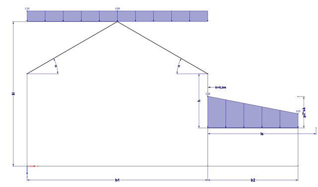
Buildings often have extensions. If the roof levels are not at the same height, this height difference (if more than 0.5 m) must additionally be considered for the snow load assumption.
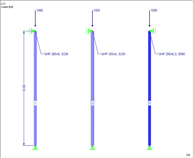
This article is about the stability analysis of a steel column with axial compression according to EN 1993‑1‑1, Clause 6.3.1. Additionally, a variation study is carried out aiming at steel optimization.

This example is described in technical literature [1] as Example 9.5 and in [2] as Example 8.5. A lateral-torsional buckling analysis must be performed for a principal beam. This beam is a uniform structural member. Therefore, the stability analysis can be carried out according to Clause 6.3.3 of DIN EN 1993‑1‑1. Due to the uniaxial bending, it would also be possible to perform the design using the General Method according to Clause 6.3.4. Additionally, the determination of the critical load factor is validated with an idealized member model in line with the method mentioned above, using an FEM model.

This example is described in technical literature [1] as Example 9.5 and in [2] as Example 8.5. A lateral-torsional buckling analysis must be performed for a principal beam. This beam is a uniform structural member. Therefore, the stability analysis can be carried out according to Clause 6.3.3 of DIN EN 1993-1-1. Due to the uniaxial bending, it would also be possible to perform the design using the General Method according to Clause 6.3.4. Additionally, the determination of the moment Mcr is validated with an idealized member model in line with the method mentioned above, using an FEM model.

Basically, you can design the structural components made of cross-laminated timber in the RF-LAMINATE add-on module. Since the design is a pure elastic stress analysis, it is necessary to additionally consider the stability issues (flexural buckling and lateral-torsional buckling).
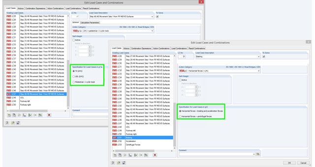
If you select the combinatorics according to EN 1990 + EN 1991‑2 and define a load case in action category gr1a, gr2, or gr5, you have to additionally define in the program which load model should be taken as a basis for the load case. This information is crucial for defining combination rules for automatic combinations according EN 1990 + EN 1991-2. In the gr1a category, you can select TS (LM1), UDL (LM1), or pedestrian and cycle track, for example. TS (LM1) is preset by default. In the gr2 category, you can select breaking and acceleration forces or centrifugal forces as a specification.